Liner Hangers

Rotating protected cemented liner hanger PHCZV

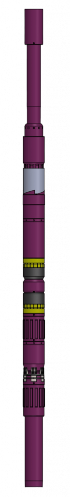
PHCZV liner hanger is used to RIH and hang cemented liners, providing the capabilities to rotate an assembly while running, hang cemented liners and allows to sequentially perform well cementing operations, set hydraulic anchor, packer and, then, disconnect a drill string. PHCZV liner hanger consists of four functionally independent components:

  • anchor to hang the liner assembly in the casing string;
  • hydro-mechanical packer to isolate annular space;
  • hydraulic release mechanism that allows to RIH liner assembly, circulate, activate anchor/packer by hydraulic pressure and, then, disconnect the drill string from PHCZV by applying hydraulic pressure.
  • mechanical disconnection that allows clockwise (to the right) assembly rotation while RIH and, at the same time, serves a backup to hydraulic disconnection. To disconnect the drill string, first, the half a turn counterclockwise turn is performed (to the left) to activate and, second, not less than 10 clockwise (to the right) turns to disconnect.

After the liner is run to the bottom and required circulations (washovers) are carried out, PHCZV activation is carried out as follows:

  • cement is pumped into a well and cement plug is lunched to separate it from displacement fluid;
  • cement slurry is displaced into the liner-open hole annular space until the plug “bumps”;
  • while well head pressure “on bump” increases, the hydraulic anchor gets set when pressure differential reaches 16 MPa;
  • hydraulic packer is activated simultaneously with anchor by differential pressure of 16 MPa;
  • when pressure differential reaches 20 MPa, the hydraulic disconnection gets activated;
  • mechanical disconnection is activated by, first rotating the drill string by 1/2 turn counterclockwise (to the left) and, second, disconnected by not less than 10 turns clockwise (to the right); • circulation/washover is performed and drill pipe is POOH.
  • washover and pulling out of the transport string.

While well casing a liner includes the following technical units:
for liner continuous cementing liner casing starter is equipped with a shoe, than check-valve and stopping branch pipe. Hanger PHCZV is mounted on the last pipe of the liner which is connected with the transport string; for liner collar cementing casing starter of liner filtering part is equipped with a shoe, above the filtering part a packer for collar cementing is mounted, PGMC, PGMC2 or PGMC4. Hanger PHCZV is mounted on the last part of the linerwhich is connected with the transport string.

PARAMETER DESCRIPTION VALUE
PHCZV. 102/146 PHCZV. 114/168-102 PHCZV. 114/168
Liner nominal diameter RIH with the device, mm 102 102 114
Diameter, recommended wall thickness (ID) of casing string which the device is run into and installed, mm 146,1
*7,7
(130,7)
168,3
*8,9
(150,5)
Maximum OD of the device body (at centralizer), mm 120 (122) 138 (141) 138 (141)
Min. drift diameter after actuation, mm 89 89 99
Maximum torque, kN*m 6 7 7
Maximum ID of a casing string in which anchoring is performed, mm 137 155 155
Values of controlling internal overpressure for actuation of units1 , MPa
– anchor unit
– packer unit
– hydraulic disconnection device
16
16
20
Maximum differential pressure between the zones isolated by a packer, MPa 15
Maximum operating temperature2 , °C 100
Maximum tensile force on the body parts3, kN 600 600 700
Connecting threads:
– top GOST 28487 (GOST R 50864)
– bottom GOST 632-80
З-86
ТМК PF 102
З-102
TMK PF 102
З-102
ОТТГ 114
Length in operating position, mm 3894 4023 4023
Weight in operating position, kg 157 182 184

1 Controlling overpressure values are given when all the shear bolts on the unit are used.
2 Reference only, depends on operating conditions of general mechanical rubber goods in a well.
3 Calculated value when stresses reach yield point of the material.

PARAMETER DESCRIPTION VALUE
PHCZV. 127/178 PHCZV. 127/178-114
Liner nominal diameter RIH with the device, mm 127 114
Diameter, recommended wall thickness (ID) of casing string which the device is run into and installed, mm 177,8
*10,4
(157)
Maximum OD of the device body (at centralizer), mm 149 (152) 149 (152)
Min. drift diameter after actuation, mm 111 99
Maximum torque, kN*m 8 8
Maximum ID of a casing string in which anchoring is performed, mm 167 167
Values of controlling internal overpressure for actuation of units1 , MPa
– anchor unit
– packer unit
– hydraulic disconnection
16
16
20
Maximum differential pressure between the zones isolated by a packer, MPa 15
Maximum operating temperature2 , °C 100
Maximum tensile force on the body parts3, kN 800 700
Connecting threads:
– top GOST 28487 (GOST R 50864)
– bottom GOST 632-80
З-102
ОТТГ-127
З-102
ОТТГ-114
Length in operating position, mm 3945 3945
Weight in operating position, kg 195 201

1 Controlling overpressure values are given when all the shear bolts on the unit are used.
2 Reference only, depends on operating conditions of general mechanical rubber goods in a well.
3 Calculated value when stresses reach yield point of the material.