


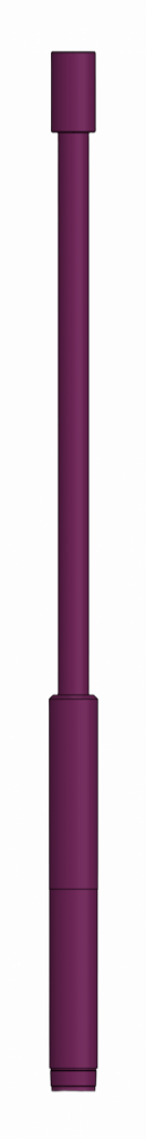
 Cemented Liner Hanger for flush-joint pipes PHCBT is applied for RIH and continuous
cementing of a liner consisting of flush-joint pipes.
The PHCBT liner hanger consists of the top sub and the body joined with the bottom sub by
special left-hand thread. There is a special groove in the body that holds the collet supported
by the piston which is held by shear bolts. There is a suspended plug positioned within the
inner channel of the device mounted with two hollow shear plugs.
The device operates as follows. While liner cementing top wiper plug is touching down the
suspended plug seat and the shearing of two hollow plugs is performed due to the pressure build-up, the access of fluid to the plunger space is opened. The pressure build-up
is performed after receiving the “stop” signal, shear bolts are ruined and plunger moves
releasing a collet. Under tension the blades of the collet clench and therefore the liner is
disconnected from the transport string.
The liner hanger is equipped with the mechanical breaking unit doubling the hydraulic one.
It is actuated by transport string rotation to the right.
The device application area is vertical, tilting (flat) wellbores and bores with horizontal ends
whereinto casing strings with diameter 102, 114, 120 and 140 mm are run in consisting of
flush-joint pipes.
Liner Hangers
- Protected liner hanger for stage cementing PHZSC
- Noncemented retrievable liner hanger PHN-E
- Noncemented liner hanger PHN1
- Noncemented liner hanger PHN2
- Noncemented liner hanger with oriented whipstock PHN-KO
- Liner hanger with disconnection before cementing PHRC
- Rotating protected cemented liner hanger PHCZV
- Protected cemented liner hanger PHCZ
- Rotating non-cemented liner hanger PHNV
- Protected hydro-mechanical cemented liner hanger PHGMCZ
- Hydro-mechanical cemented liner hanger PHGMC
- Cemented liner hanger for flush-joint pipes PHCBT
- Liner hanger assembly, revolving while cementing PHVC
- Liner Hanger with two kinds of release before cementing PHGMRC
Cemented liner hanger for flush-joint pipes PHCBT
| PARAMETER DESCRIPTION | VALUE | |||
| PHCBT. 102/140 |
PHCBT. 114/140 |
PHCBT. 120/146 |
PHCBT. 140/168 |
|
| Liner nominal diameter RIH with the device, mm | 102 | 114 | 120 | 140 |
| Maximum OD of the device, mm | 108 | 120 | 123 | 144 |
| Drift diameter of the device, mm | 86,5 | 98,5 | 105 | 124 |
| Diameter of a hole in a plug seat, mm | 30 | 40 | 40 | 40 |
| Maximum internal pressure of the device body, MPa | 25 | 25 | 25 | 25 |
| Length of the device fully assembled, mm | 2105 | 2105 | 2105 | 2105 |
| Weight of the device, kg | 45 | 78 | 73,35 | 78,1 |
| Maximum tensile force1 , kN (tn) |
600 (60) | 700 (70) | 770 (77) | 900 (90) |
| Maximum operating temperature2 , °C |
100 | 100 | 100 | 100 |
| Connecting threads: – top GOST 633 – bottom TR 14-157-61-99 |
73 ТМК-3 |
73 ТМК-3 |
73 ТМК-3 |
73 ТМК-3 |
1
Calculated value when stresses reach yield point of the material.
2
Reference only, depends on operating conditions of general mechanical rubber goods in a well.